Post-Operative Arrhythmia Monitoring – Current Practice
Abnormal heart rhythms (arrhythmia) are common after heart surgery and are associated with increased morbidity, mortality and cost. Unfortunately, in many cases, the standard practice of displaying surface electrograms (ECG)s on the bedside monitor does not provide adequate clarity of the atrial signals to accurately identify the heart rhythm.
Surface ECG Monitoring for Post-Operative Arrhythmia
The ECG signal displays the electrical difference between any two of the electrodes, such as the right arm (RA) and left leg (LL). Each time the heart beats, electricity moves through the heart causing the heart muscle to contract. The electrical difference between the electrodes changes and is reflected by upwards or downward deflections as the electricity moves towards or away from the lead axis. The ventricles are much larger and display an easily identifiable ventricular signal on the ECG. However, especially during higher heart rates, the much smaller atrial signal can be challenging or impossible to identify. The inability to accurately identify the atrial signals can result in missed or inaccurate rhythm diagnosis.
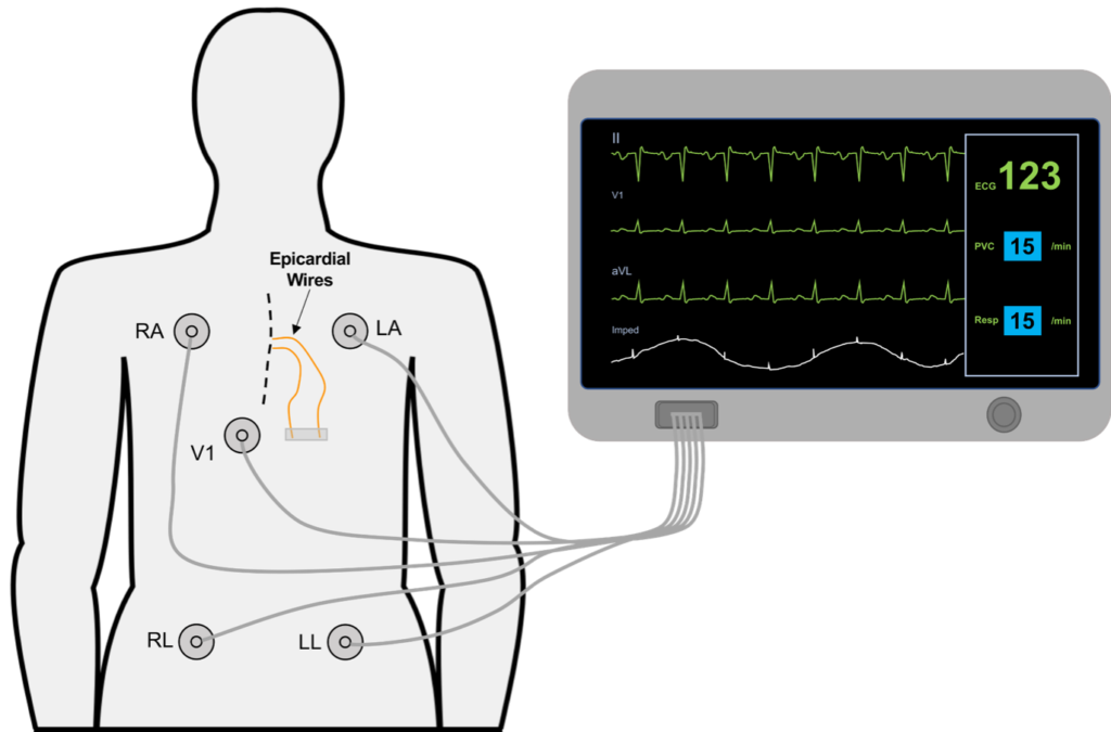
In the figure above the electrodes on the surface of the chest are used to display the patients ECG on the bedside monitor. The temporary atrial epicardial wires, placed at the time of surgery are shown but not in use.

Unfortunately, due to the smaller atrial signals on the surface ECG, it may be impossible to accurately identify the atrial signals. Without the ability to identify both the atrial and ventricular signals, post-operative rhythms can be difficult or impossible to diagnose. This can result in delayed or missed diagnosis.

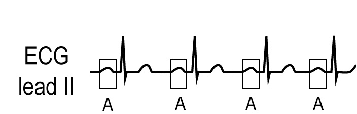
The Atrial Electrogram provides a better way to identify post-operative arrhythmia
The Atrial Electrogram (AEG) is considered the highest quality signal for rhythm identification due to it’s ability to easily identify the atrial signals. Because of this, the AEG is recommended by the American Heart Association for optimal rhythm identification (AHA Practice Standards for Electrocardiographic Monitoring in Hospital Settings). The AEG can be displayed continuously on the bedside monitor using the AtriAmp, or on a 10 second 12 lead ECG.
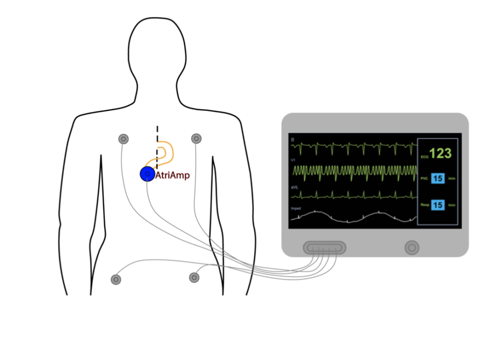
Continuous AEG display on the bedside monitor
The AtriAmp is a single use device to continuously display atrial electrogram signals on the bedside monitor. To display the atrial electrogram, the limb leads are attached to the skin in their appropriate position (RA/LA/RL/LL) as when monitoring from the surface leads only. The AtriAmp is then attached to the atrial epicardial wires and the bedside monitor precordial chest (V) lead as recommended by the manufacturer. The monitor is then set to display a surface electrogram (i.e. lead II) and the precordial AtriAmp lead (V). The precordial lead now displays a continuous atrial electrogram on chest (V) lead as shown below. In this example, the figure shows a rapid atrial fibrillation/flutter on the AEG displayed on V1.
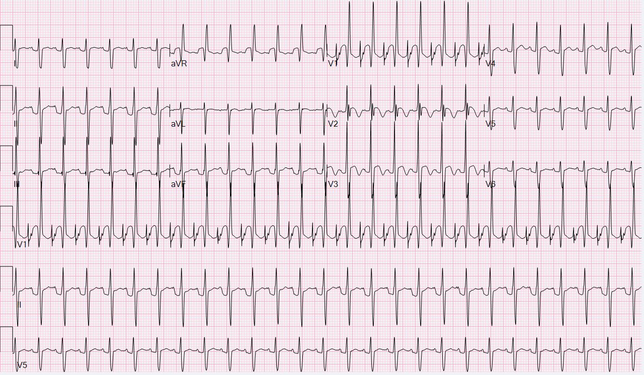
AEG display on a standard 10 second ECG
The Atrial Electrogram can also be obtained by attaching the atrial epicardial wires to a standard 12 or 15 lead ECG as shown below. The 12 or 15 lead ECG is attached in the standard fashion after attaching the surface electrodes with the exception of the V1 lead. Instead of attaching to the precordium, the V1 lead is attached to the atrial epicardial wire. In the below example the V1 signal is the Atrial electrogram. Unfortunately, adapting the 12 lead ECG can take substantial time waiting for the 12 lead ECG, is not displayed continuously and may result in missed diagnosis and delayed treatment.
Once the atrial signals are displayed, identification of the atrial and ventricular signals can begin.